Explanation Of The Feeding Time,Picking Stroke, And Opening Time Of The Shuttle Loom
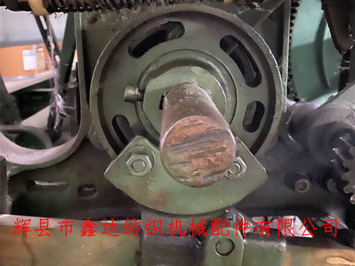
The feeding time, picking stroke, and opening time of a shuttle loom are the basic knowledge for loom maintenance. We need to carefully study and understand the feeding time, feeding stroke, and opening process of the loom, so as to lay a solid theoretical foundation for future machine maintenance work and quickly analyze the location of faults.
1.The shuttle feeding time refers to when the loom starts to feed the shuttle, that is, when the shuttle feeding rotor and shuttle feeding nose start to contact. The shuttle feeding time is usually expressed by the distance from the reed to the weaving edge or the reed to the inner edge of the chest beam at the beginning of shuttle feeding.
2. The shuttle throw stroke refers to the action stroke of the shuttle rod pushing the skin knot, usually used to represent the speed obtained by the shuttle.
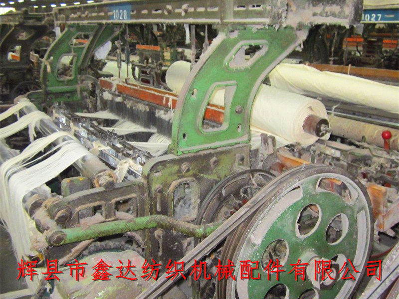
3. Opening time, also known as comprehensive leveling time, indicates the timing of the shuttle opening and closing. The opening time is generally expressed in terms of the distance between the reed and the weaving mouth or the distance between the reed and the inner edge of the chest beam. To determine the opening time, two aspects should be considered comprehensively: first, there should be a longer effective opening time. The effective shuttle opening referred to here refers to the shuttle opening that does not touch the warp yarn during flight. It is not only related to the size of the opening, but also to the front and rear positions of the seat. On the other hand, during the beating process, the warp yarn has an appropriate amount of unequal tension at the opening, allowing each beating to form a normal fabric. These two requirements are contradictory to each other. In order to meet the flight conditions of the shuttle, if the midpoint of the fully open stationary angle of the opening pedal is set at the rear dead center of the crankshaft, the effective shuttle opening time will be longer. But with this configuration, the overall leveling time happens to be during the weaving process. At this point, the tension difference between the upper and lower warp yarns is zero, making it difficult for the weft yarns to tighten, and the beating area will expand, even to the point where it cannot be woven properly. On the contrary, if we only consider the difference in warp tension, it will inevitably excessively reduce the effective shuttle opening time, which is not conducive to shuttle flight.
There is a close relationship between shuttle time, shuttle travel, and opening time. To determine these three parameters reasonably, the first step is to select the appropriate opening time. For example, when the opening time is set to 232 millimeters, that is, the crank position is at 274 °; The shuttle throwing time is 232 millimeters, which means the crank position is 84 degrees; The shuttle travel is 195 millimeters, the loom speed is 200 revolutions per minute, and 23 × 21 flat fabrics are woven. When the crank is rotated to the front dead center 0 °, the opening of the shuttle opening has exceeded 80%. Such a large unequal tension shuttle opening can certainly meet the needs of weaving, but when the crank is rotated to around 30 °, the shuttle opening is already full, and the steel reed only retreats 20 millimeters from the weaving opening, making it impossible for the shuttle to pass through. It is not until the crankshaft rotates to 120 ° that an effective shuttle opening appears on the shuttle plate, and at 230 °, the effective shuttle opening begins to contract again. In fact, the effective shuttle opening only has a rotation angle of 110 °. We used a flash tester to calculate the flight trajectory of the shuttle in the above process scheme, as shown in curve 1 of Figure 1-2.
It ranges from 84 to 120 degrees, with a shuttle travel of 210 millimeters, indicating that the shuttle is not compressed by the warp yarn when entering the shuttle opening; 84~230 °, shuttle travel is 1240 millimeters. According to calculations, during this period, if the shuttle is not compressed by the warp yarn, it needs to travel more than 1400 millimeters. So curve 1 indicates that about 160 millimeters of the shuttle exit in this scheme is compressed by the warp yarn.
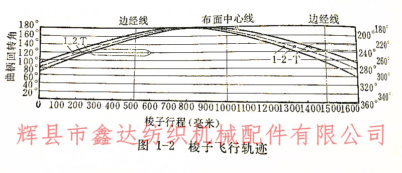
The curve T in Figure 1-2 is the flight trajectory that ensures that the shuttle is not compressed by the warp yarn when entering and exiting the shuttle port. This plan has a significant shuttle travel, resulting in high material and power consumption for the shuttle mechanism.
If the opening time is set to 229 millimeters (9 inches), which is 276 degrees; The shuttle throwing time is set at 222 millimeters, which is 77 degrees; The shuttle travel is 180 millimeters. When used on the same loom as above, the shuttle flight trajectory is shown in curve 2: the crank rotates from 77 ° to 120 °, and the shuttle travel is 240 millimeters. This indicates that the shuttle was not squeezed by the warp yarn when entering the shuttle port. 77~230 °, with a shuttle travel of 1260 millimeters, indicating that the exit of the shuttle is also subjected to compression with a travel of 140 millimeters. But this plan reduces the shuttle travel by 15 millimeters, which is beneficial for reducing machine material and power consumption.
From the comparison of the above several process parameter configuration schemes, it can be seen that the reasonable determination of the size and economic value of process parameters. Of course, the relationship between the opening time, shuttle feeding time, shuttle feeding stroke, and shuttle flight is complex and may vary in actual production depending on vehicle speed, machine condition, and fabric variety. But one thing is certain, they are dominated by the opening time, and the shuttle feeding time and stroke are correspondingly coordinated, with the aim of extending the effective shuttle opening as much as possible while meeting the weaving conditions, ensuring that the shuttle entering the shuttle opening is not squeezed, the shuttle exit is less squeezed, and striving to reduce the consumption of machine materials and power. The precautions when adjusting the three parameters are:
1.Correct the opening time. Place the shuttle on one side of the shuttle box according to regulations, with the crank near the upper center, and measure the distance between the reed and the inner edge of the chest beam. Place the fabric roller on the surface of the fabric, squat down and loosen the plain weave tread plate screws (remove the gear cover 634 from the twill weave fabric, loosen the split gear screws), so that the two tread rods A2 × 3 are level (the twill weave fabric should be level with the two tread rods according to the process requirements), then tighten the screws (the twill weave fabric should be installed with the cover), and still put the fabric roller back in place.
2.School shuttle travel. Rotate the crankshaft to press the shuttle nose F4 on the side plate Q12 to a low position, loosen the bolt F1 of the side plate cap sleeve, adjust the lower screws of the side plate hanging feet F6 and F7, measure the distance between the inner side of the shuttle plate and the inner end of the shuttle box bottom plate according to the process specifications, and then tighten the screw nut of the side plate cap sleeve and the lower screws of the fixed side plate hanging feet F6 and F7.
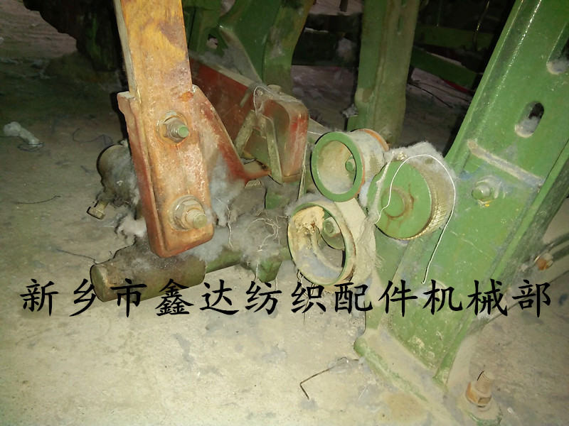
3.Correct shuttle feeding time. Rotate the crankshaft near the lower center and measure the distance between the reed surface and the inner edge of the chest beam P3 according to the specified dimensions in the process; Loosen the screw core F13 nut of the shuttle feeding rotor slightly, pull the shuttle feeding plate to the outside, so that the shuttle feeding rotor F11 and the shuttle feeding nose F4 are just in contact, and then tighten the screw core nut of the shuttle feeding rotor. To facilitate tightening the core nut, a rolling block should be inserted between the 36 teeth and 72 teeth.
4.First, calibrate the shuttle throw stroke, and then calibrate the shuttle throw time. The order of the two cannot be reversed, otherwise after the shuttle feeding time is calibrated, the shuttle travel should be calibrated by moving the position of the side plate fulcrum, which will cause the calibrated shuttle feeding time to change again.
5.Under normal conditions, increasing the shuttle throw will inevitably increase the shuttle flight speed accordingly. But in some special cases, such as when the arc-shaped curve of the shuttle nose F4 is worn too much, the side plate is too soft, or the side plate and side plate guide plate collide with each other, simply increasing the shuttle throw cannot significantly increase the shuttle flight speed. Therefore, when repairing the machine, it is necessary to pay attention to these abnormal situations, promptly eliminate them, and then adjust the shuttle throw.


