Installation Requirements And Standards For 1515 Loom Foot Thread

The installation requirements and standards for the foundation wire of the 1515 weaving machine are the same as those of the 1511 type and GA615. We analyze the dimensions of the foundation wire at various levels through pictures, provide detailed installation instructions for the foundation wire, and also carefully describe the inspection methods after the foundation wire is installed. We are willing to learn and exchange ideas with colleagues in Guangzhou Textile.

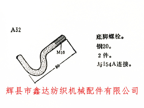
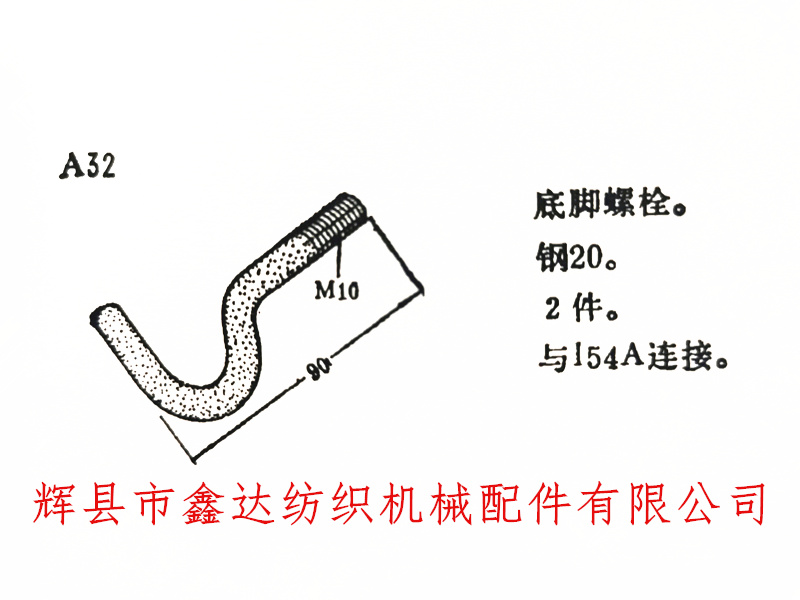
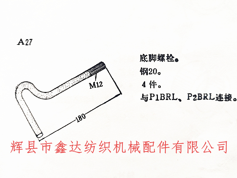
The foot wire of the weaving machine is divided into two specifications.1515 Power Loom Foot screws, Loom Foot Screws, Loom Installation,The A32 in the above picture is a short foot wire used for the foot installation of the I54 weaving machine's fuse box support. The following picture shows the anchor wire A27 we used to fix the weaving machine wall panel:

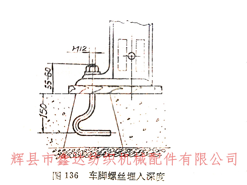
The A27 bottom bolt of the weaving machine, also known as the anchor wire, can be used for various models of shuttle looms and rapier looms. The specific installation requirements and standards are: the anchor pit is in the shape of a circular cone, the side section is trapezoidal (as shown in the figure below), the screw of the anchor wire is based on a diameter of 12 millimeters, and the length of the anchor wire protruding from the ground is recommended to be 55-60 millimeters. The burial depth underground shall not be less than 150 millimeters. After burying the anchor wire, its verticality shall be checked, and the angle ruler shall be used to check if it is less than 1 millimeter. The difference in center distance between the four anchor wires shall also be controlled within 1mm.

In order to reduce the vibration of the 1515 machine during operation, prevent the wall panel foot from breaking, and ensure the smooth operation of the whole machine, the floor board needs to be in full contact with the wall panel foot, and the nut of the foot wire also needs to be locked. After adjusting the pedal shaft and tightening the foot screws, use a 0.2mm micrometer to insert and test around the upper and lower sides of the foot board (the upper plane of the floor board). The insertion depth should be less than 6mm, and the width should be less than 13mm on the top and 25mm on the bottom. Please use this standard for judgment. If it does not meet this industry standard, the floor board needs to be corrected again. Please refer to the previous chapter for details on the steps.


