1515 Type 214M Multi Shuttle Loom Accessories Sketch Book (B, C)

Our company collates all kinds of 1515 model 214M multi shuttle Loom accessories sketch book (thumbnail) photos to facilitate customers to accurately identify the multi shuttle machine part code, part number, MG sketch, including 1515 Loom wallboard external transmission parts (214M-B) and multi shuttle box accessories drawings (214M-C). For specific parameters, please refer to the corresponding pictures in the article.
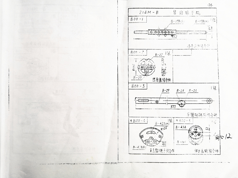
B00-1 grid square joint, B00-2 four corner plate joint, B00-3 reverse steel root ladder joint, B00-4 foot peach joint, B00-5 extension gear joint.

B00-6 shuttle box screw assembly, B00-7 pagoda tooth assembly (R/L), B00-8 Lackball assembly, B00-9 striker frame assembly, B00-11 bolt assembly, B00-13 positioning arm assembly, etc.
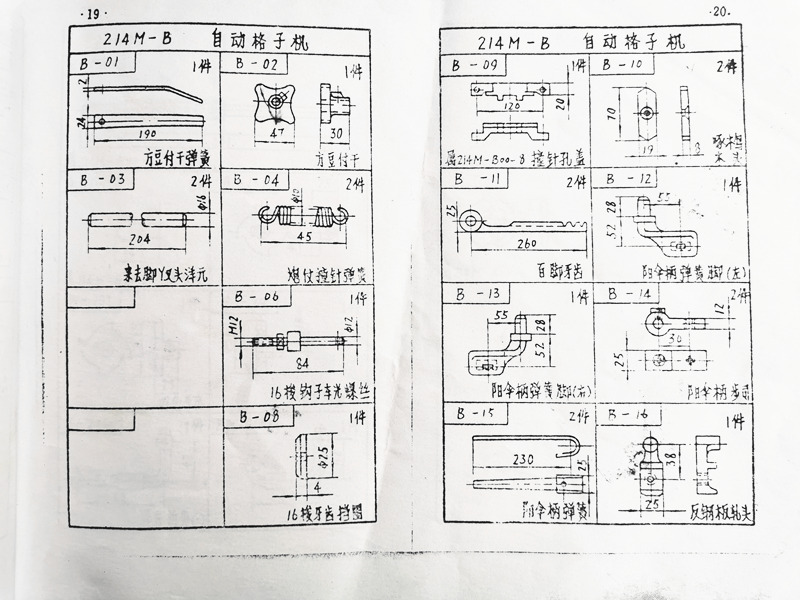
B-01 square tofu dried spring, B-02 square tofu dried spring, B-03 coming and going feet Y-fork head Yang Yuan, B-04 gun gun firing needle spring, B-08 shuttle tooth retaining ring, B-10 woodpecker wood, B-12 umbrella handle spring foot, B-16 reverse steel plate rolling head.
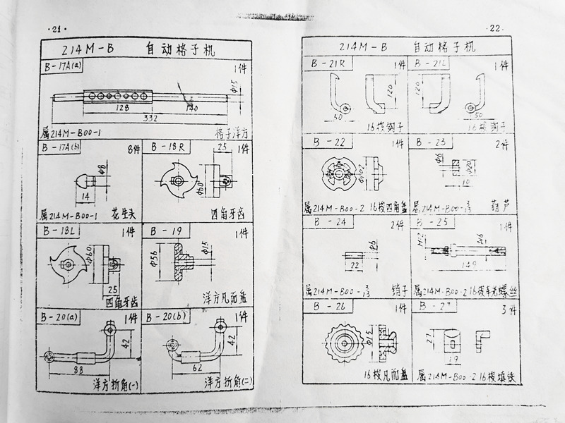
B-18 four corner teeth, B-20 square folding angle, B-21 16 shuttle hook, B-26 16 shuttle valve plate, B-17 peanut head.
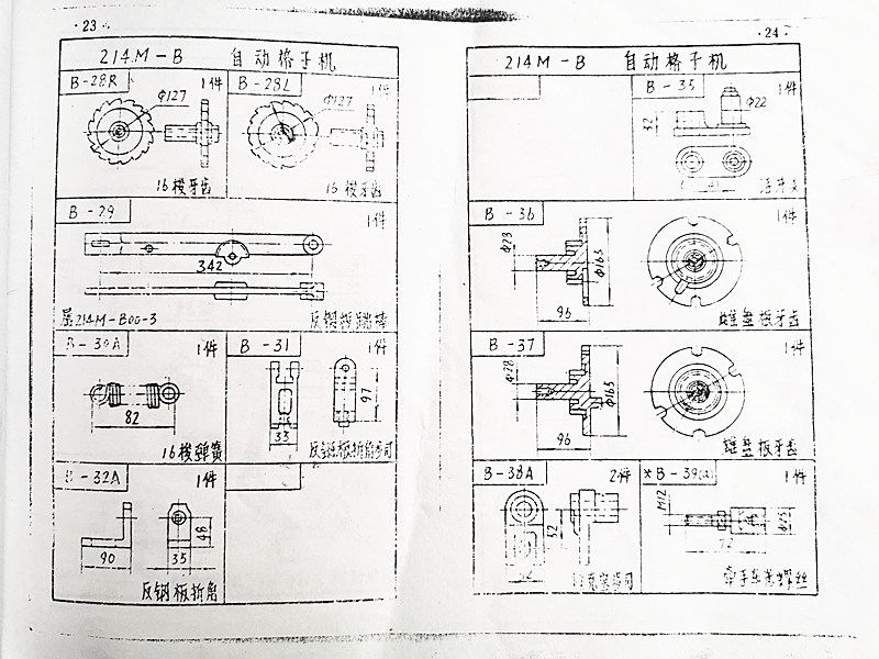
B-29 anti steel plate jumping rod, B-32 anti steel plate folding angle, B-36 female disc plate teeth, B-37 male disc plate teeth, B-39 hand held turning screw, B-38 Lacubus.
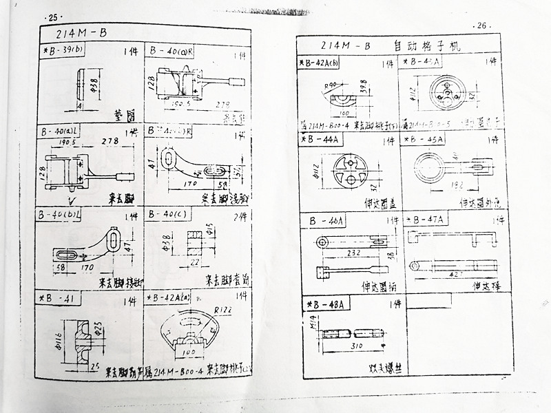
B-40 come and go foot, B-40 come and go foot copper sleeve, B-44 extension ring cover, B-47 extension rod, B-48 double head screw, B-41 come and go foot hoist.
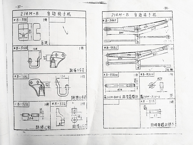
Drawing of B-50 pressing block, schematic diagram of B-51 jumping rod, B-54 jumping rod, B-55 lifting hook box screw parameters, B-57 lifting hook box screw pin size.
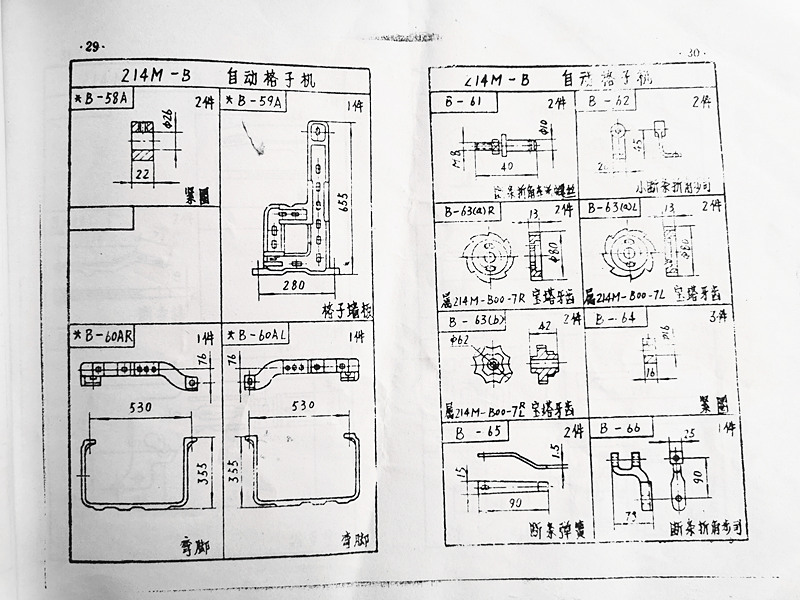
B-60 bent foot, B-59 grid wall panel, B-63 pagoda tooth size, B-66 broken bar corner step, B-65 broken bar spring drawing.
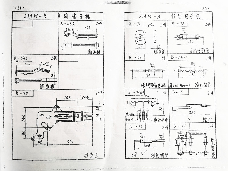
Thumbnails of B-68 Broken Bar, B-70 Lackball Sketch, B-75 Multi Shuttle Striker Drawing, B-74 Striker Holder, B-71 Inkstone Table Dimensions.
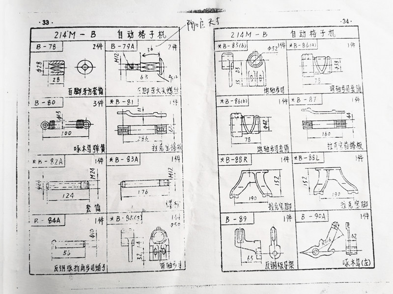
B-85 curved shaft stepper, B-81 Lacquer wall panel, B-80 Woodpecker spring, B-78 Hundred foot Teeth Square Sleeve, B-87 Lacquer front landing plate.
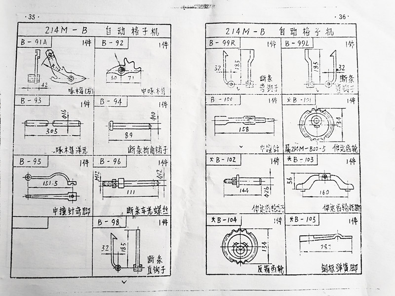
B-93 Woodpecker Yang Yuan, B-98 Broken Bar Straight Hook, B-104 Reverse Box Gear, B-101 Extension Gear Sketch, B-105 Steel Plate Spring Foot.
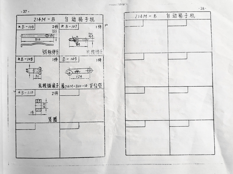
B-110 tightening ring, B-108 rolling hook pin roller, B-106 steel plate spring size, B-107 rolling hook pin outline drawing.
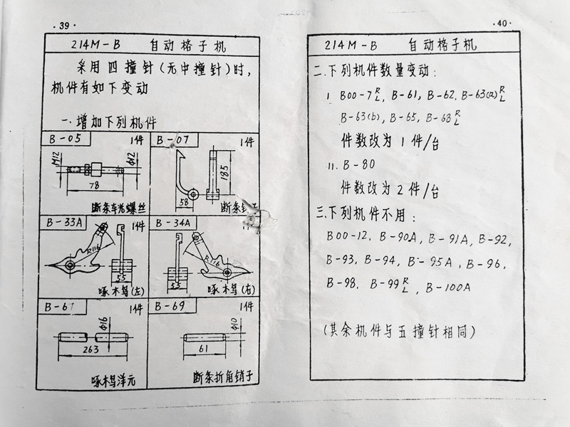
Instructions for 214M-B 1X4 Automatic Lattice Machine Accessories
The following is a thumbnail of the 214M-C 1X4 shuttle box machine, with detailed assembly drawings, part numbers, and dimensions:
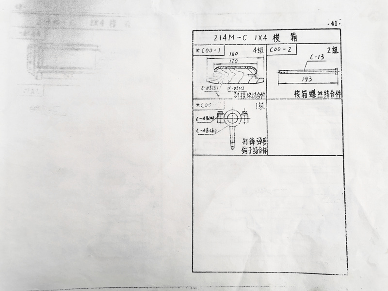
C00-1 shuttle block assembly, C00-2 shuttle box screw assembly, C00-3 shuttle box spring hook assembly
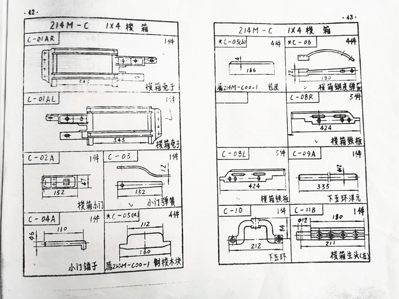
C-01 shuttle box shell drawing, C-02 shuttle box small door parameters, C-03 small Ting spring, C-05 made shuttle wood block, C-06 shuttle box steel sheet spring size, C-08 shuttle box iron plate, C-09 lower five ring Yang Yuan, C-11 shuttle box raw head (divided into left and right)
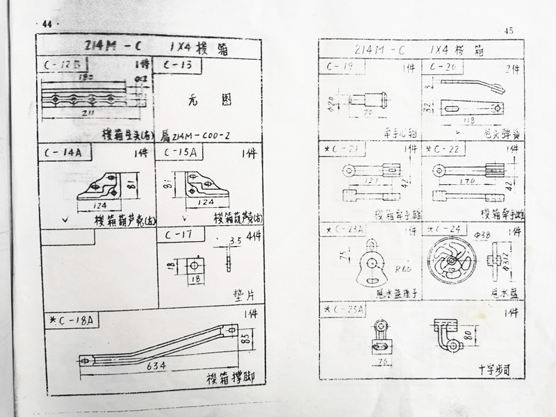
C-14 shuttle box hoist shell, C-18 shuttle box support foot, C-20 wrapped head spring diagram, C-23 water splash plate seat, C-25 cross step size
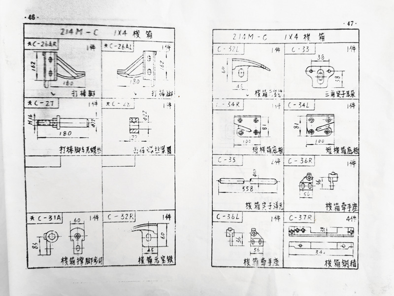
C-26 beater foot, C-27 beater foot turning screw, C-28 tightening ring, C-35 shuttle box stator element, C-36 shuttle box handle seat, C-32 shuttle box element Baotie
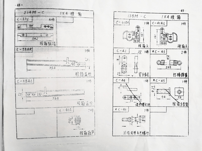
C-43 rod spring, C-42 stator stepper, C-38 shuttle box cover plate, C-40 shuttle box hoist, C-44 adjusting screw block
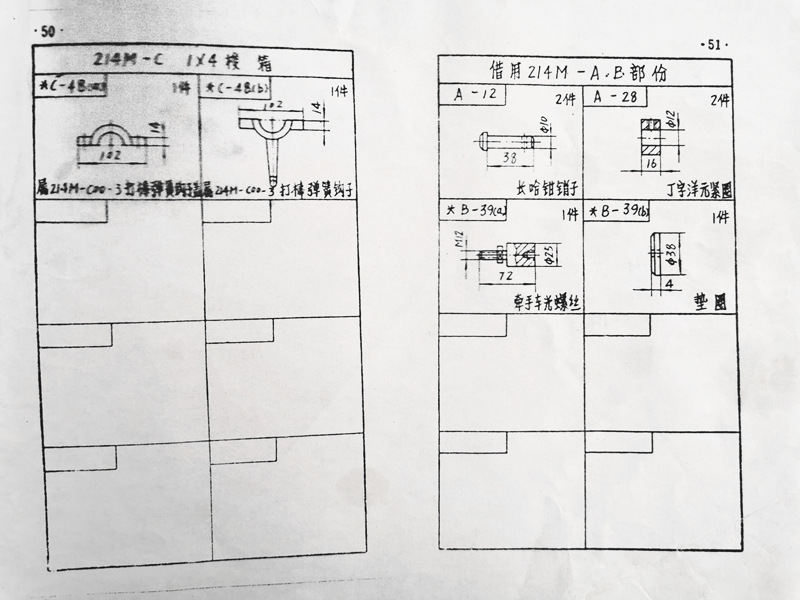
The above is a schematic diagram of the 214M automatic lattice machine device, the transmission components of the 214M-B lattice, and the structural diagram of the 214M-C lattice shuttle box, which is convenient for peers to learn and reference.
Download detailed information:


